
Introduction
In this post I’ll show you an implementation of a Carrier-of-Carriers Inter-provider Layer-3 VPN on Junos vMX. I’ve studied this stuff as the last topic explained on Juniper Networks JNCIS-IS MPLS Study Guide, which I suggest you to read if you want to understand a lot of interesting features of Juniper platform.
This is the topology of the lab (click on this link for the full-size image):

As you can see in the image above, I’ve used a convention to number the Loopback and P-t-P interfaces of the routers: it seems complex, but you’ll get used after a while 🙂
Some examples:
- Loopback of CE-SP-PE7: router Rx is within group 1 (the number within the golden square) and x is equal to 7, so its loopback is 192.168.1.7/32
- Interface of CE-A-11 toward CE1-SP-PE7: it is an inter-group P-t-P link, between R11 and R7, so it is within 172.16.*.* network. Given that one of the two router’s numbers is greater than 10, we’ll sum 11 and 7, so we have 18 as the third octet. The IP address is 172.16.18.11/24. The interface is blue, so it is lt-0/0/10.117 with peer unit lt-0/0/10.711: unit is 117 because we are on router with ID 11 and the interface points toward router with ID 7 (so the router with ID 7 will have unit 711 paired with unit 117 for the same logic)
- Interface of SP-P1 toward SP-PE2: it is an intra-group P-t-P link, between R1 and R2, so it is within 10.*.*.* network. Group is 0 so the second octet is 0. The third octet is given by XY, where X is the lowest-numbered router, R1 and Y is the higher-numbered router, R2. So the third octet is 12. The last octet is given by the router number of SP-P1, so the ip address is 10.0.12.1/24. The interface is green, so it is ge-0/0/0.12 with vlan-id 12: ge-0/0/0 because we are on router with ID 1 facing on the link toward router with ID 2, so we use the ge-0/0/0; unit is 12 and vlan-id is the same, and it is the concatenation of the two IDs, the lowest first, since both are less than 10. The corresponding interface on router with ID 2 is ge-0/0/1.12 with vlan-id 12.
As you can see, we’ll use /24 networks even if they are P-t-Ps, just to have the possibility to implement our numbering scheme.
On each link I’ve put one or more letters M, L or R to quickly show which protocols among MPLS, LDP and RSVP are enabled and running on the links.
Route-Distinguishers and Route-Targets used for the L3-VPNs are shown in the graphic.
The whole topology has been built on a single Juniper vMX virtual router, running within EVE-NG. Blue links are built on lt-0/0/10 logical tunnel interface, while green links are built on ge-0/0/0 and ge-0/0/1 physical interfaces, which are connected one with each other. A pair of ge interfaces are sufficient to build how many P-t-P links we want, it is sufficient to use a different vlan-id for each link. The reason why I’ve inserted some ge links is that EVE-NG allows me to capture packets on that links, while it wouldn’t be possible on the lt-0/0/10 interface. The fact that I’ve used only a pair of ge interfaces instead of more is that sniffing on ge-0/0/0 interface allows me to see the traffic traversing the 4 segments in a row, with different vlan tags.
This is the lab on EVE-NG (em0 is the management interface connected to my LAN):

The switch cloud on the right is a simple way to connect ge-0/0/0 with ge-0/0/1 using EVE-NG linux bridging facility, without the need to configure a virtual switch.
Objective: Service provider 1 and 2 want to offer a L3-VPN called vpn-a between CE-A-11 and CE-A-12. The two service providers have different AS Numbers and are interconnected by Service Provider 0 which will offer them an Inter-Provider vpn called inter-vpn.
Problem: vpn-a L3-VPN must be established with an MP-EBGP session between the two ASBRs of SP1 and SP2. No other router in SP1, SP2 and SP0 will know anything about vpn-a. We must build a label-switched-path from CE1-SP-PE7 and CE2-SP-PE10. Usually IPv4 (family inet) i/eBGP sessions do not attach a label to the routes sent to the neighbors. This would imply that CE1-SP-PE7 would receive a route to reach CE2-SP-PE10 loopback without a label attached to it: this would cause the sending of a packet labeled with a vpn-a vpn label to CE1-SP-PE5, which as I’ve previously said doesn’t know anything about the vpn-a L3-VPN and would discard the packet. The same for the other routers in the path toward destination.
Carrier-of-Carriers Service Provider L3-VPN
Service Provider 0 is configured with OSPF Area 0 as IGP. I’ve chosen to use RSVP to build the following LSPs, instead of enabling LDP:
- Bidirectional LSPs between SP-PE2 and SP-PE3 routers: these LSPs are needed to resolve the next-hop of inter-vpn L3-VPN routes in inet.3.
- Unidirectional LSP from SP-RR4 Route-Reflector toward its RR-clients: these LSPs are needed because routes received by an RR that can not resolve the corresponding next-hop in inet.3 are hidden and thus not “reflected” to other clients.
Each of SP-PE2 and SP-PE3 routers have an MP-iBGP session with SP-RR4, which has only the inet-vpn family enabled, since we only need to carry labeled L3-VPN routes. SP-P1 is a P-router, and it doesn’t need to know anything about VPN routes, so it requires only to run OSPF, MPLS and RSVP on its interfaces, to allow the building of the required RSVP LSPs that I’ve mentioned above.
The only routes that we need to have within the inter-vpn.inet.0 table on SP-PE2 and SP-PE3 are the loopback addresses of CE1-SP-PE7 and CE2-SP-PE10, which will need to reach each other to build the outermost MP-eBGP session for vpn-a. P-t-P links in the inter-vpn routing-instance are not sent as labeled VPN routes between over the MP-iBGP session between SP-PE2 and SP-PE3, because they are considered multi-access links and are only advertised if there is a route with a next-hop on that link or if we’re using vrf-table-label within the routing-instance (which is not the case for inter-vpn).
Follows the output of some show commands executed for the routers within SP0:
-- SP-PE2 --
admin> show route logical-system SP-PE2

inet.0: 9 destinations, 9 routes (9 active, 0 holddown, 0 hidden)
+ = Active Route, - = Last Active, * = Both

10.0.12.0/24 *[Direct/0] 01:14:57
 > via ge-0/0/1.12
10.0.12.2/32 *[Local/0] 01:14:59
 Local via ge-0/0/1.12
10.0.13.0/24 *[OSPF/10] 01:14:43, metric 2
 > to 10.0.12.1 via ge-0/0/1.12
10.0.14.0/24 *[OSPF/10] 01:14:43, metric 2
 > to 10.0.12.1 via ge-0/0/1.12
192.168.0.1/32 *[OSPF/10] 01:14:43, metric 1
 > to 10.0.12.1 via ge-0/0/1.12
192.168.0.2/32 *[Direct/0] 01:15:43
 > via lo0.2
192.168.0.3/32 *[OSPF/10] 01:14:33, metric 2
 > to 10.0.12.1 via ge-0/0/1.12
192.168.0.4/32 *[OSPF/10] 01:14:38, metric 2
 > to 10.0.12.1 via ge-0/0/1.12
224.0.0.5/32 *[OSPF/10] 01:15:46, metric 1
 MultiRecv

inet.3: 1 destinations, 1 routes (1 active, 0 holddown, 0 hidden)
+ = Active Route, - = Last Active, * = Both

192.168.0.3/32 *[RSVP/7/1] 01:14:16, metric 2
 > to 10.0.12.1 via ge-0/0/1.12, label-switched-path from-SP-PE2-to-SP-PE3

inter-vpn.inet.0: 4 destinations, 4 routes (4 active, 0 holddown, 0 hidden)
+ = Active Route, - = Last Active, * = Both

172.16.25.0/24 *[Direct/0] 01:14:58
 > via ge-0/0/0.25
172.16.25.2/32 *[Local/0] 01:14:59
 Local via ge-0/0/0.25
192.168.1.7/32 *[BGP/170] 01:14:35, localpref 100
 AS path: 65100 I, validation-state: unverified
 > to 172.16.25.5 via ge-0/0/0.25, Push 299824
192.168.2.10/32 *[BGP/170] 01:14:16, localpref 100, from 192.168.0.4
 AS path: 65200 I, validation-state: unverified
 > to 10.0.12.1 via ge-0/0/1.12, label-switched-path from-SP-PE2-to-SP-PE3
[...]

admin> show mpls lsp logical-system SP-PE2 ingress detail
Ingress LSP: 1 sessions

192.168.0.3
 From: 192.168.0.2, State: Up, ActiveRoute: 0, LSPname: from-SP-PE2-to-SP-PE3
 ActivePath: (primary)
 LSPtype: Static Configured, Penultimate hop popping
 LoadBalance: Random
 Encoding type: Packet, Switching type: Packet, GPID: IPv4
 *Primary State: Up
 Priorities: 7 0
 SmartOptimizeTimer: 180
 Computed ERO (S [L] denotes strict [loose] hops): (CSPF metric: 2)
 10.0.12.1 S 10.0.13.3 S
 Received RRO (ProtectionFlag 1=Available 2=InUse 4=B/W 8=Node 10=SoftPreempt 20=Node-ID):
 10.0.12.1 10.0.13.3
Total 1 displayed, Up 1, Down 0

-- SP-RR4 --
admin> show route logical-system SP-RR4 table inet.3

inet.3: 2 destinations, 2 routes (2 active, 0 holddown, 0 hidden)
+ = Active Route, - = Last Active, * = Both

192.168.0.2/32 *[RSVP/7/1] 01:18:23, metric 2
 > to 10.0.14.1 via lt-0/0/10.41, label-switched-path from-SP-RR4-to-SP-PE2
192.168.0.3/32 *[RSVP/7/1] 01:18:22, metric 2
 > to 10.0.14.1 via lt-0/0/10.41, label-switched-path from-SP-RR4-to-SP-PE3

admin> show route logical-system SP-RR4 table bgp.l3vpn.0

bgp.l3vpn.0: 2 destinations, 2 routes (2 active, 0 holddown, 0 hidden)
+ = Active Route, - = Last Active, * = Both

65000:2:192.168.1.7/32
 *[BGP/170] 01:18:47, localpref 100, from 192.168.0.2
 AS path: 65100 I, validation-state: unverified
 > to 10.0.14.1 via lt-0/0/10.41, label-switched-path from-SP-RR4-to-SP-PE2
65000:3:192.168.2.10/32
 *[BGP/170] 01:18:43, localpref 100, from 192.168.0.3
 AS path: 65200 I, validation-state: unverified
 > to 10.0.14.1 via lt-0/0/10.41, label-switched-path from-SP-RR4-to-SP-PE3

-- SP-P1 (only inet.0 and mpls.0 routes) --
admin> show route logical-system SP-P1 terse | match routes

inet.0: 11 destinations, 11 routes (11 active, 0 holddown, 0 hidden)

mpls.0: 12 destinations, 12 routes (12 active, 0 holddown, 0 hidden)
Service Provider 1
Now let’s have a look to SP1 (which is configured as SP2): again, we have OSPF running on the three nodes and LSPs between CE1-SP-PE7 and CE1-SP-PE5, this time built by LDP instead of RSVP. As we’ve previously said, we need to have a Label-Switched-Path that spans across different Autonomous-Systems, so we must find a way for the 192.168.2.10/32 route of CE2-SP-PE10 loopback to flow through SP2, the inter-vpn on SP0 and then SP1 toward CE1-SP-PE7 with a label attached to it: this is accomplished through two BGP sessions, an MP-eBGP session between SP0 and SP1 and an MP-iBGP session within SP1, as shown on the topology, both with labeled-unicast feature enabled within inet address family. This feature tells the router to attach a label to the IPv4 route that sends to the BGP neighbor. I’ll show you the route to 192.168.2.10/32 on different routers, with the label(s) attached to it:
-- SP-PE3 inter-vpn.inet.0: route with the label attached by CE2-SP-PE8 due to labeled-unicast --
admin> show route logical-system SP-PE3 table inter-vpn.inet.0 192.168.2.10/32

inter-vpn.inet.0: 4 destinations, 4 routes (4 active, 0 holddown, 0 hidden)
+ = Active Route, - = Last Active, * = Both

192.168.2.10/32 *[BGP/170] 01:32:39, localpref 100
 AS path: 65200 I, validation-state: unverified
 > to 172.16.38.8 via lt-0/0/10.38, Push 299824

-- SP-PE2 inter-vpn.inet.0: route with the L3-VPN label attached to the route by SP-PE3 and the RSVP LSP label on top of it to reach SP-PE3 (some lines are omitted for brevity) --
admin> show route logical-system SP-PE2 table inter-vpn.inet.0 192.168.2.10/32 detail

inter-vpn.inet.0: 4 destinations, 4 routes (4 active, 0 holddown, 0 hidden)
192.168.2.10/32 (1 entry, 1 announced)
 *BGP Preference: 170/-101
 Source: 192.168.0.4
 Next hop: 10.0.12.1 via ge-0/0/1.12, selected
 Label-switched-path from-SP-PE2-to-SP-PE3
 Label operation: Push 299776, Push 299824(top)
 Protocol next hop: 192.168.0.3
 VPN Label: 299776

-- CE1-SP-PE5 inet.0: route with the label attached by SP-PE2 due to labeled-unicast --

admin> show route logical-system CE1-SP-PE5 table inet.0 192.168.2.10/32

inet.0: 10 destinations, 11 routes (10 active, 1 holddown, 0 hidden)
+ = Active Route, - = Last Active, * = Both

192.168.2.10/32 *[BGP/170] 01:32:44, localpref 100
 AS path: 65000 65200 I, validation-state: unverified
 > to 172.16.25.2 via ge-0/0/1.25, Push 299808

-- CE1-SP-PE7 inet.0: route with the label attached by CE1-SP-PE5 due to labeled-unicast and the top label of the LSP toward CE1-SP-PE5 --

admin> show route logical-system CE1-SP-PE7 table inet.0 192.168.2.10/32

inet.0: 8 destinations, 8 routes (8 active, 0 holddown, 0 hidden)
+ = Active Route, - = Last Active, * = Both

192.168.2.10/32 *[BGP/170] 01:32:54, localpref 100, from 192.168.1.5
 AS path: 65000 65200 I, validation-state: unverified
 > to 10.1.67.6 via ge-0/0/1.67, Push 299840, Push 299792(top)
I’ve omitted the route as it is seen on CE2-SP-PE8: in this case we receive a labeled IPv4 BGP route (preference 170) for 192.168.2.10/32 from CE2-SP-PE10, but it is also received in OSPF (preference 10), so the installed route has no label: this would cause a problem when CE1-SP-PE7 sends a packet with a vpn-a MPLS label, because when it reaches CE2-SP-PE8 it would be forwarded to CE2-SP-P9 toward CE2-SP-P10 with only the vpn-a label, which would be unknown to CE2-SP-P9. We must force the iBGP labeled route to be installed in CE2-SP-PE8 inet.0 table (even if the label is an explicit null, as we will see, but having a BGP route instead of an OSPF one forces the use of the LSP toward CE2-SP-P10 to deliver the packet, thus adding an additional label that will be popped by CE2-SP-P9), so I’ve raised OSPF preference to 200:
-- CE2-SP-PE8 --

admin> show route logical-system CE2-SP-PE8 table inet.0 192.168.2.10/32

inet.0: 10 destinations, 11 routes (10 active, 1 holddown, 0 hidden)
+ = Active Route, - = Last Active, * = Both

192.168.2.10/32 *[BGP/170] 01:47:34, localpref 100, from 192.168.2.10
 AS path: I, validation-state: unverified
 > to 10.2.89.9 via lt-0/0/10.89, Push 299776
 [OSPF/200] 01:47:37, metric 2
 > to 10.2.89.9 via lt-0/0/10.89
Label 299776 is not the label attached to the route by CE2-SP-PE10, but it is the label used to reach the next-hop 192.168.2.10, resolved via inet.3 table:
admin> show route logical-system CE2-SP-PE8 table inet.3

inet.3: 2 destinations, 2 routes (2 active, 0 holddown, 0 hidden)
+ = Active Route, - = Last Active, * = Both

192.168.2.9/32 *[LDP/9] 10:12:23, metric 1
 > to 10.2.89.9 via lt-0/0/10.89
192.168.2.10/32 *[LDP/9] 10:12:23, metric 2
 > to 10.2.89.9 via lt-0/0/10.89, Push 299776
CE2-SP-PE10 in fact sends a labeled route to CE2-SP-PE8 but the label is an explicit null (reserved label 3), which means “you do not have to use a label to reach that route, just reach me”:
admin> show route logical-system CE2-SP-PE8 receive-protocol bgp 192.168.2.10 extensive

inet.0: 10 destinations, 11 routes (10 active, 1 holddown, 0 hidden)
* 192.168.2.10/32 (2 entries, 2 announced)
 Accepted
 Route Label: 3
 Nexthop: 192.168.2.10
 Localpref: 100
 AS path: I
In fact, a packet received by CE2-SP-PE8 directed to CE2-SP-PE10 vpn-a needs only the vpn-a label and on top of it a label to reach CE2-SP-PE10 via an LDP LSP. The outer label will then be removed by CE2-SP-P9 due to Penultimate-Hop-Popping and a packet with only the VPN label will be delivered to CE2-SP-P10.
VPN-A customer’s L3VPN between SP1 and SP2
As a final step, once that we have a bidirectional LSP between CE1-SP-PE7 and CE2-SP-PE10, we can build the vpn-a L3VPN with an MP-eBGP session between those two routers. In order to make the vpn-a work, as we’ve explained with inter-vpn, we need to have the eBGP next-hop reachable in inet.3 routing table. This is accomplished with the addition of resolve-vpn keyword added to labeled-unicast, which forces labeled IPv4 routes to be installed also in inet.3. Follows the configuration of BGP (internal and external BGP) on CE1-SP-PE7 and the configuration of the routing-instance for vpn-a, where I’ve used vrf-table-label (which forces a lookup in the vpn-a.inet.0 routing table instead of directly sending VPN packets destined to CE-A-11 on the P-t-P interface) and static routing to reach the loopback of the connected CEs of Customer A (the CEs in turn have a default route toward their Service Provider):
-- CE1-SP-PE7 --
admin> show configuration logical-systems CE1-SP-PE7 protocols bgp
group SP1-Internal {
 type internal;
 local-address 192.168.1.7;
 family inet {
  labeled-unicast {
   resolve-vpn;
  }
 }
 export export-loopback;
 neighbor 192.168.1.5;
}
group SP-1-2-external {
 type external;
 multihop;
 local-address 192.168.1.7;
 family inet-vpn {
  unicast;
 }
 peer-as 65200;
 neighbor 192.168.2.10;
}

admin> show configuration logical-systems CE1-SP-PE7 routing-instances vpn-a
instance-type vrf;
interface lt-0/0/10.711;
route-distinguisher 65012:100;
vrf-target target:65012:0;
vrf-table-label;
routing-options {
 static {
  route 192.168.4.11/32 next-hop 172.16.18.11;
 }
}
Follows the output of some show commands on the same router, that shows the use of 3 labels, label 16 is a VPN label (it is so low due to the vrf-table-label statement), 299840 is the label attached to 192.168.2.10/32 route sent by CE1-SP-PE5 to CE1-SP-PE7 and 299792 is the LDP label associated to the LSP toward CE1-SP-PE5:
-- CE1-SP-PE7 --
admin> show route logical-system CE1-SP-PE7 table vpn-a.inet.0

vpn-a.inet.0: 5 destinations, 5 routes (5 active, 0 holddown, 0 hidden)
+ = Active Route, - = Last Active, * = Both

172.16.18.0/24 *[Direct/0] 00:01:32
 > via lt-0/0/10.711
172.16.18.7/32 *[Local/0] 02:18:07
 Local via lt-0/0/10.711
172.16.22.0/24 *[BGP/170] 00:01:32, localpref 100, from 192.168.2.10
 AS path: 65200 I, validation-state: unverified
 > to 10.1.67.6 via ge-0/0/1.67, Push 16, Push 299840, Push 299792(top)
192.168.4.11/32 *[Static/5] 00:01:32
 > to 172.16.18.11 via lt-0/0/10.711
192.168.4.12/32 *[BGP/170] 00:01:32, localpref 100, from 192.168.2.10
 AS path: 65200 I, validation-state: unverified
 > to 10.1.67.6 via ge-0/0/1.67, Push 16, Push 299840, Push 299792(top)
As you can see, the reception of label 16 forces a second lookup within vpn-a.inet.0 routing table, instead of directly sending the packet toward CE-A-11 on the lt-0/0/10.711 interface of CE1-SP-PE7:
admin> show route logical-system CE1-SP-PE7 table mpls.0 label 16

mpls.0: 8 destinations, 8 routes (8 active, 0 holddown, 0 hidden)
+ = Active Route, - = Last Active, * = Both

16 *[VPN/0] 21:14:18
 to table vpn-a.inet.0, Pop
Verifying the connection between CE-A-11 and CE-A-12
Now it is time to verify the connectivity between the two Customer-A’s routers with a traceroute. In order to have information for every hop within the network, each MPLS-enabled router must have icmp-tunneling enabled within protocol mpls stanza, otherwise a packet with an expired Time-To-Live value within IP header would produce a reply toward the source of the packet, 192.168.4.11 for example, which is completely unknown to all the routers except SP1 and SP2 ASBRs, i.e. CE1-SP-PE7 and CE2-SP-10. Enabling icmp-tunneling forces the router where the packet is expired to build an ICMP response that is sent toward the destination instead of the source with the original MPLS tags. When it reaches, in our example, CE2-SP-PE10 within vpn-a.inet.0 table the router sees that the destination is 192.168.4.11 and it is sent back toward the source of the traceroute’s UDP packet. I’ll add some info about each label on every hop.
admin> traceroute logical-system CE-A-11 192.168.4.12 source 192.168.4.11
traceroute to 192.168.4.12 (192.168.4.12) from 192.168.4.11, 30 hops max, 40 byte packets

 1 172.16.18.7 (172.16.18.7) 1.237 ms 0.668 ms 0.545 ms

 2 10.1.67.6 (10.1.67.6) 3.833 ms 4.254 ms 3.706 ms
 MPLS Label=299792 CoS=0 TTL=1 S=0 => LDP label to reach CE1-SP-PE5
 MPLS Label=299840 CoS=0 TTL=1 S=0 => iBGP label-unicast label for 192.168.4.12 received from CE-SP-PE5
 MPLS Label=16 CoS=0 TTL=1 S=1 => vpn-a label received from 192.168.4.12

3 10.1.56.5 (10.1.56.5) 3.704 ms 4.209 ms 3.687 ms => PHP removes the outermost label
 MPLS Label=299840 CoS=0 TTL=1 S=0
 MPLS Label=16 CoS=0 TTL=2 S=1

4 172.16.25.2 (172.16.25.2) 3.770 ms 4.368 ms 3.605 ms
 MPLS Label=299792 CoS=0 TTL=1 S=0 => eBGP label-unicast label for 192.168.4.12 received from SP-PE2. It replaced label 299840
 MPLS Label=16 CoS=0 TTL=3 S=1

5 10.0.12.1 (10.0.12.1) 5.300 ms 5.557 ms 3.600 ms
 MPLS Label=299824 CoS=0 TTL=1 S=0 => RSVP label for from-SP-PE2-to-SP-PE3 LSP toward 192.168.0.3
 MPLS Label=299776 CoS=0 TTL=1 S=0 => inter-vpn label for 192.168.4.12 received from 192.168.0.3 through Route-Reflector 192.168.0.4. This replaces label 299792
 MPLS Label=16 CoS=0 TTL=4 S=1

6 10.0.13.3 (10.0.13.3) 4.809 ms 3.749 ms 4.161 ms => PHP removes the outermost label
 MPLS Label=299776 CoS=0 TTL=1 S=0
 MPLS Label=16 CoS=0 TTL=5 S=1

7 172.16.38.8 (172.16.38.8) 3.610 ms 4.518 ms 3.661 ms
 MPLS Label=299824 CoS=0 TTL=1 S=0 => eBGP label-unicast label for 192.168.4.12 received from CE2-SP-PE8. It replaced label 299776
 MPLS Label=16 CoS=0 TTL=6 S=1

8 10.2.89.9 (10.2.89.9) 3.633 ms 4.246 ms 3.619 ms => third label not added due to the explicit-null label received for 192.168.4.12 from 192.168.2.10 through iBGP labeled-unicast route advertisement
 MPLS Label=299776 CoS=0 TTL=1 S=0 => LDP label to reach CE2-SP-PE10. It replaced label 299824
 MPLS Label=16 CoS=0 TTL=7 S=1

9 172.16.22.10 (172.16.22.10) 4.002 ms 4.404 ms 3.705 ms => PHP removed the outermost label. CE2-SP-PE10 received the packet only with label 16 that has been removed for a second lookup within vpn-a.inet.0 due to vrf-table-label

10 192.168.4.12 (192.168.4.12) 4.000 ms 3.831 ms 4.493 ms
Then, I’ve started a packet capture on ge-0/0/0 interface within EVE-NG and run the following command on vMX:
admin> ping logical-system CE-A-12 192.168.4.11 source 192.168.4.12 count 1
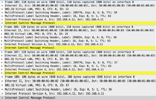
As you can see from the image below, I’ve captured the same echo request and echo reply packets 4 times in a row:

Looking at the echo request packets, you can see all the labels we’ve seen from the traceroute output before (look at the vlan-id, it tells you the green link the packet is traversing):
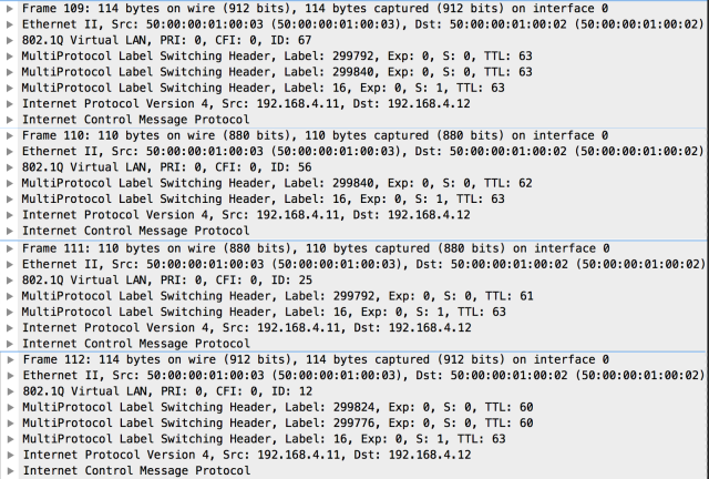
These are the replies captured on the same interface (I’ll show you also the replies because they show the triple-label stack when the packet is leaving the L3VPN routing instance in CE1-SP-PE7 and SP-PE2):
vMX Configuration
You can find the full configuration of the lab that you can load within your vMX router. Adjust the IP address of em0 interface, which is the one that can be connected to the Net cloud connected to the real LAN if you want to manage vMX via SSH. You can upload the configuration file via SSH (copy and paste via console can give you buffer problems) and then load it with the following commands:
[edit]
admin# delete
This will delete the entire configuration
Delete everything under this level? [yes,no] (no) yes

admin# load merge carrier-of-carriers_vMX_topology.cfg
load complete

admin# commit

commit complete
User is admin with password admin1, root has password root123.
carrier-of-carriers_vMX_topology.cfg
Conclusion
I hope you’ve read the whole stuff, it has been a long post but I hope you’ve find the topic very interesting as I did. I suggest you to read the JNCIS-SP Study Guide available from Juniper Networks to understand a lot of interesting stuff about MPLS on Junos, which can be successfully tested on a vMX platform.
As I usually say, post comments or questions or even tell me if I’ve made some mistakes, I’ve just gone through this stuff for few days and there is sure room to improve my skills 🙂

Really good detailed post – great to have the config as well 🙂 Sorry might sound like a dumb question but what steps do you take to create that UNL lab ‘Net to vMX em0/fxp0’ connection i.e the mgmt. connection to allow direct SSH from my desktop PC to the vMX (as loading configs in via terminal is buffer limited for some reason). I’m using EVE-NG in (the free) VMware player. Cheers
LikeLike
Hi Simon,
create a new lab, add a Network node with Type set to pnet0, which is the bridge with eth0 of EVE-NG vm that is connected to your LAN (set the connection in bridged mode within VMWare) and than connect the network cloud you’ve just created with the vMX em0 interface. Launch vMX and do the minimal setup which involves giving an IP address to em0 that works on your lan (or enable DHCP on that interface) and you should be able to do SSH from your network to the vMX. Then patch my cfg and replace the IP I’ve given to em0 with the IP address you’ve chosen before, upload the patched cfg via SCP, delete the whole configuration and load (merge) my cfg. Tell me if it is clear now 🙂
LikeLike
Cheers Gianni, I had been connecting my em0/fxp0 to pnet1! I had a full core setup already and had been using HTML5 console access or SSH access via the UNL port but as mentioned the buffer issues cause headaches (adding two lines at a time or free typing config was painful). Now its all clear I was going to quickly use your config to take look at the carrier of carriers setup in a new lab. Good stuff. Many thanks 🙂
LikeLiked by 1 person
Hey Gianni, I had some problem in vMX,while setuping the basic lab … I have created two logical-system in single vMX with lt-0/0/10 interface but they couldn’t ping each other, Could you please help me. below is the configuration for reference (My vMX is running in eve-ng )
NOTE:–My vMX router did not show the lt interface units under respective logical-system
root@JUNIPER-LAB# show
## Last changed: 2018-08-11 02:12:31 UTC
version 14.1R1.10;
system {
host-name JUNIPER-LAB;
root-authentication {
encrypted-password “$1$.cB5Dcp0$iixtcaf6LQ7xQrTz9sEvr1”; ## SECRET-DATA
}
syslog {
user * {
any emergency;
}
file messages {
any notice;
authorization info;
}
file interactive-commands {
interactive-commands any;
}
}
}
logical-systems {
JunosR1;
JunosR2;
junosR1 {
interfaces {
lt-0/0/10 {
unit 1 {
encapsulation ethernet;
peer-unit 2;
family inet {
address 172.16.12.1/24;
}
}
}
}
}
junosR2 {
interfaces {
lt-0/0/10 {
unit 2 {
encapsulation ethernet;
peer-unit 1;
family inet {
address 172.16.12.2/24;
}
}
}
}
}
}
chassis {
fpc 0 {
pic 0 {
tunnel-services {
bandwidth 1g;
}
}
}
}
[edit]
root@JUNIPER-LAB
root@JUNIPER-LAB# show | display set
set version 14.1R1.10
set system host-name JUNIPER-LAB
set system root-authentication encrypted-password “$1$.cB5Dcp0$iixtcaf6LQ7xQrTz9sEvr1”
set system syslog user * any emergency
set system syslog file messages any notice
set system syslog file messages authorization info
set system syslog file interactive-commands interactive-commands any
set logical-systems JunosR1
set logical-systems JunosR2
set logical-systems junosR1 interfaces lt-0/0/10 unit 1 encapsulation ethernet
set logical-systems junosR1 interfaces lt-0/0/10 unit 1 peer-unit 2
set logical-systems junosR1 interfaces lt-0/0/10 unit 1 family inet address 172.16.12.1/24
set logical-systems junosR2 interfaces lt-0/0/10 unit 2 encapsulation ethernet
set logical-systems junosR2 interfaces lt-0/0/10 unit 2 peer-unit 1
set logical-systems junosR2 interfaces lt-0/0/10 unit 2 family inet address 172.16.12.2/24
set chassis fpc 0 pic 0 tunnel-services bandwidth 1g
[edit]
root@JUNIPER-LAB# …2.16.12.2 logical-system junosR1 source 172.16.12.1
ping: bind: Can’t assign requested address
[edit]
root@JUNIPER-LAB# …2.16.12.1 logical-system junosR2 source 172.16.12.2
ping: bind: Can’t assign requested address
[edit]
root@JUNIPER-LAB# run show interfaces terse | match lt
lt-0/0/10 up up
root@JUNIPER-LAB# run show chassis hardware
Hardware inventory:
Item Version Part number Serial number Description
Chassis VMX
Midplane
Routing Engine RE-VMX
CB 0 VMX SCB
FPC 0 10x1G FPC
CPU Rev. 1.0 RIOT 123XYZ987
MIC 0 Virtual 10x1GE PIC
PIC 0 BUILTIN BUILTIN Virtual 10x1GE PIC
LikeLike