
Introduction: The Topology
A lot of time has passed since my last post on this blog and I’m back with something about an interesting feature, LFA, i.e. Loop-Free Alternate, this time not implemented on Cisco routers but on Juniper ones. I’ve used the following topology, implemented with logical systems, i.e. virtual routers inside a JunOS vMX instance.
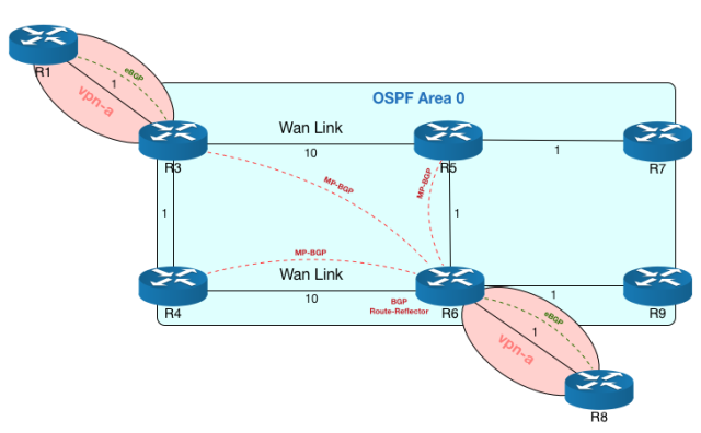
We have 4 main core routers, R3-R4-R5-R6, forming a square, in OSPF area 0.0.0.0, along with other two routers, R7-R9. OSPF link costs are depicted on the image.
Routers R1 and R8 are connected to R3 and R6, respectively, in a routing-instance of type vrf with route-target 1000:1, thus forming a L3-VPN.
I’ve not put IPs on the topology diagram but IP assignment is simple and follows these rules:
- Loopback Addresses: they take the form of 100.0.0.x with x the number of the router. So R5 has 100.0.0.5 as loopback address
- P-t-P link Subnet: even if a /30 would be sufficient, we use a /24 network, which allows us to use the scheme 10.0.xy.0/24, where x is the number of the lowest-numbered router connected to the P-t-P link and y is the number of the highest-numbered router connected to the P-t-P link. So the link between R3 and R5 has the network 10.0.35.0/24. OSPF configuration forces P-t-P link type.
- P-t-P link interface address: on a P-t-P link 10.0.xy.0/24 router Rx has address 10.0.xy.x and router Ry has address 10.0.xy.y
Since these routers are logical-systems, they are connected one with each other with logical units under the logical-tunnel interface lt-0/0/10 with the following rule:
- Rx is connected to Ry with lt-0/0/10.xy paired with lt-0/0/10.yx, which is the other end of the tunnel that connects Ry with Rx
So, for example, R3 is connected with R1 with the following interface and IP address:
interfaces {
  lt-0/0/10 {
    unit 31 {
      encapsulation ethernet;
      peer-unit 13;
      family inet {
        address 10.0.13.3/24;
      }
      family mpls;
    }
  }
}
MPLS, RSVP, LDP are enabled on all the interface of routers within OSPF area 0.0.0.0.
Finally, core routers have load-balance per-packet (which is per-flow, despite the name) applied on the forwarding table, so equal-cost paths are load-balanced when taking forwarding decisions.
The Feature: Loop-Free Alternate
In this post we get the focus on router R3 and think about what we can do to improve convergence time in the square topology of core routers when R3 WAN’s link fails and it needs to get to the routers on the other side. Standard OSPF convergence allows for quite fast convergence time in case of a link failure, but there is still an interruption in traffic flow across the WAN for R3, if R3-R5 fails. We will see why R3 can not immediately start forwarding to R4 and how we can force it to immediately forward thorough that neighbor the traffic destined to R5 or R7, without causing loops, and LFA will be the feature of our interest.
Simple OSPF deployment
Let’s have a look at the routing table of R3, focusing on loopback addresses with a simple OSPF deployment:
admin> show route logical-system R3 table inet.0 100.0.0.0/24

inet.0: 15 destinations, 15 routes (15 active, 0 holddown, 0 hidden)
+ = Active Route, - = Last Active, * = Both

100.0.0.3/32 *[Direct/0] 01:55:14
             > via lo0.3
100.0.0.4/32 *[OSPF/10] 01:54:16, metric 1
             > to 10.0.34.4 via lt-0/0/10.34
100.0.0.5/32 *[OSPF/10] 01:24:38, metric 10
             > to 10.0.35.5 via lt-0/0/10.35
100.0.0.6/32 *[OSPF/10] 01:24:38, metric 11
             > to 10.0.34.4 via lt-0/0/10.34
               to 10.0.35.5 via lt-0/0/10.35
100.0.0.7/32 *[OSPF/10] 01:24:38, metric 11
             > to 10.0.35.5 via lt-0/0/10.35
100.0.0.9/32 *[OSPF/10] 01:24:38, metric 12
               to 10.0.34.4 via lt-0/0/10.34
             > to 10.0.35.5 via lt-0/0/10.35
As you can see, R3 can reach R6 (and, obviously, R9) through two equal-cost paths, through its neighbors R4 and R5, so if R3-R4 goes down, R3 can immediately forward traffic to R6 (and R9) that was previously forwarded to R4, to the neighbor R5 (because it immediately knows that R3-R5 is down, being connected to that link). If the link that gets broken is the WAN link, i.e. R3-R5, R3 can not immediately forward traffic destined to R5 (and R7) to neighbor R4, because it knows that until SFP runs and the network converges, traffic could loop. In fact, R4 has two equal paths to R5, through R3 and R6, so if it receives traffic destined to R5 (and R7) from R3, it could send it back to R3 until it knows that R3-R5 is down and it has only one path, through R6, to R5. So, if WAN link between R3 and R5 goes down, we must wait for the network to converge before traffic flowing from R3 and R5 starts flowing again toward the destination.
OSPF Link Protection
We can enable link-protection on ospf links in order to make ospf find alternate backup paths that it can use as soon as an ospf link fails. This is the explanation for the feature taken from juniper.net site:
You can configure link protection for any interface for which OSPF is enabled. When you enable link protection, Junos OS creates an alternate path to the primary next hop for all destination routes that traverse a protected interface. Use link protection when you assume that only a single link might become unavailable but that the neighboring node would still be available through another interface.
We can query ospf spf data to see what R3 knows about destination R6:
admin> show ospf backup spf detail logical-system R3 100.0.0.6
Topology default results:

Area 0.0.0.0 results:

100.0.0.6
 Self to Destination Metric: 11
 Parent Node: 100.0.0.5
 Parent Node: 10.0.46.6
 Primary next-hop: lt-0/0/10.34 via 10.0.34.4
 Primary next-hop: lt-0/0/10.35 via 10.0.35.5
 Backup Neighbor: 100.0.0.5
  Neighbor to Destination Metric: 1, Neighbor to Self Metric: 10
  Self to Neighbor Metric: 10, Backup preference: 0x0
  Not evaluated, Reason: Primary next-hop multipath
 Backup Neighbor: 100.0.0.4
  Neighbor to Destination Metric: 10, Neighbor to Self Metric: 1
  Self to Neighbor Metric: 1, Backup preference: 0x0
  Not evaluated, Reason: Primary next-hop multipath
The output says that both paths are already primary paths and so link-protection does not add anything, as I’ve already said, to network performance in case of link failure.
Let’s look at destination R7:
admin> show ospf backup spf detail logical-system R3 100.0.0.7
Topology default results:

Area 0.0.0.0 results:

100.0.0.7
 Self to Destination Metric: 11
 Parent Node: 100.0.0.5
 Primary next-hop: lt-0/0/10.35 via 10.0.35.5
 Backup Neighbor: 100.0.0.5
  Neighbor to Destination Metric: 1, Neighbor to Self Metric: 10
  Self to Neighbor Metric: 10, Backup preference: 0x0
  Not eligible, Reason: Primary next-hop link fate sharing
 Backup Neighbor: 100.0.0.4
  Neighbor to Destination Metric: 12, Neighbor to Self Metric: 1
  Self to Neighbor Metric: 1, Backup preference: 0x0
  Track Item: 100.0.0.3
  Track Item: 100.0.0.5
  Not eligible, Reason: Path loops
In this case, the first backup neighbor is the same neighbor through which we reach 100.0.0.7, i.e. 100.0.0.5 (Primary next-hop link fate sharing, which means that if primary next-hop fails, also that backup neighbor will not be usable). The second backup neighbor, R4, could be an alternate path, but as we discussed before, it would cause a traffic loop (Path loops).
So, with link-protection OSPF can immediately start to work about finding feasible successors, using an EIGRP terminology, i.e. a successor where we can immediately route traffic flowing on a link that fails and that was the best path toward a destination. Again, this does not add almost anything to our network due to our topology, so let’s move to the next step to decrease traffic disruption in case of link R3-R5 failure.
RSVP-TE tunnel from R3 to R5
How can we help R3 to forward traffic destined to R5 and R7 through R4->R6->R5 path without causing a loop? We must use something that forces R4 not to do a lookup on traffic destination, otherwise it could route it back to R3 until knows about the link failure. We can deploy an RSVP-TE tunnel from R3 to R5 that goes through R4: in this way, R3 encapsulates traffic within an MPLS label which is swapped by R4 (popped due to PHP, i.e. Penultimate-Hop-Popping) without looking at the contents of the forwarded packets, which are de-encapsulated at R6 and forwarded to R5, without enabling loops.
Let’s define the RSVP-TE tunnel on R3:
protocols {
  mpls {
    icmp-tunneling;
    label-switched-path to-R6 {
      backup;
      to 100.0.0.6;
      primary loose-R4;
    }
    path loose-R4 {
      100.0.0.4 loose;
    }
    interface all;
  }
}
This is the defined path:
admin> show mpls lsp logical-system R3 detail
Ingress LSP: 1 sessions

100.0.0.6
 From: 100.0.0.3, State: Up, ActiveRoute: 0, LSPname: to-R6
 ActivePath: loose-R4 (primary)
 LSPtype: Static Configured, Penultimate hop popping
 LoadBalance: Random
 Encoding type: Packet, Switching type: Packet, GPID: IPv4
 *Primary loose-R4 State: Up
 Priorities: 7 0
 SmartOptimizeTimer: 180
 Computed ERO (S [L] denotes strict [loose] hops): (CSPF metric: 11)
 10.0.34.4 S 10.0.46.6 S
 Received RRO (ProtectionFlag 1=Available 2=InUse 4=B/W 8=Node 10=SoftPreempt 20=Node-ID):
 10.0.34.4 10.0.46.6
Total 1 displayed, Up 1, Down 0
As the ERO (Explicit Route Object) says, the path goes on R3-R4 and R4-R6 links. As you can see in path definition, we added the keyword backup to let ospf use that RSVP tunnel for alternate path computations. Let’s look again at spf backup coverage for destination 100.0.0.7:
admin> show ospf backup spf detail logical-system R3 100.0.0.7
Topology default results:

Area 0.0.0.0 results:

100.0.0.7
 Self to Destination Metric: 11
 Parent Node: 100.0.0.5
 Primary next-hop: lt-0/0/10.35 via 10.0.35.5
 Backup next-hop: to-R6
 Backup Neighbor: 100.0.0.6 (LSP endpoint)
  Neighbor to Destination Metric: 2, Neighbor to Self Metric: 11
  Self to Neighbor Metric: 11, Backup preference: 0x0
  Track Item: 100.0.0.5
  Eligible, Reason: Contributes backup next-hop
 Backup Neighbor: 100.0.0.5
  Neighbor to Destination Metric: 1, Neighbor to Self Metric: 10
  Self to Neighbor Metric: 10, Backup preference: 0x0
  Not evaluated, Reason: Interface is already covered
 Backup Neighbor: 100.0.0.4
  Neighbor to Destination Metric: 12, Neighbor to Self Metric: 1
  Self to Neighbor Metric: 1, Backup preference: 0x0
  Track Item: 100.0.0.3
  Track Item: 100.0.0.5
  Not evaluated, Reason: Interface is already covered
Now, as you can see from the following output, ospf perfectly knows that if primary next-hop on lt-0/0/10.35 fails, due to link R3-R5 failure, it can immediately encapsulate traffic within RSVP tunnel and forward it on R3-R4 link. R3 route table now has alternate next-hops listed also for 100.0.0.5 and 100.0.0.7:
admin> show route logical-system R3 table inet.0 100.0.0.0/24

inet.0: 15 destinations, 15 routes (15 active, 0 holddown, 0 hidden)
+ = Active Route, - = Last Active, * = Both

100.0.0.3/32 *[Direct/0] 04:00:44
             > via lo0.3
100.0.0.4/32 *[OSPF/10] 03:59:46, metric 1
             > to 10.0.34.4 via lt-0/0/10.34
100.0.0.5/32 *[OSPF/10] 00:08:29, metric 10
             > to 10.0.35.5 via lt-0/0/10.35
               to 10.0.34.4 via lt-0/0/10.34, label-switched-path to-R6
100.0.0.6/32 *[OSPF/10] 00:47:34, metric 11
               to 10.0.34.4 via lt-0/0/10.34
             > to 10.0.35.5 via lt-0/0/10.35
100.0.0.7/32 *[OSPF/10] 00:08:29, metric 11
             > to 10.0.35.5 via lt-0/0/10.35
               to 10.0.34.4 via lt-0/0/10.34, label-switched-path to-R6
100.0.0.9/32 *[OSPF/10] 00:47:34, metric 12
             > to 10.0.34.4 via lt-0/0/10.34
               to 10.0.35.5 via lt-0/0/10.35
We focused on R3, but the same approach should be taken also on R4-R5-R6, defining link-protection and an RSVP-TE tunnel to the not-directly connected router on the opposite vertex of the square on each core router.
Now you could be asking yourself “why did he implement also a L3-VPN in the topology”? We will see it in the next section.
RSVP-TE tunnel and load-balancing vpn-a traffic
Let’s disable for a moment RSVP-TE tunnel from R3 to R5 and have a look at vpn-a.inet.0 routing table on R3 for 100.0.0.8 destination, i.e. CE router R8, connected to R6 (some lines are omitted for brevity):
admin> show route logical-system R3 table vpn-a.inet.0 100.0.0.8/32 detail

vpn-a.inet.0: 5 destinations, 5 routes (5 active, 0 holddown, 0 hidden)
100.0.0.8/32 (1 entry, 1 announced)
 *BGP Preference: 170/-101
 Route Distinguisher: 1000:1000
 Next hop type: Indirect
 Next hop type: Router, Next hop index: 1048592
 Next hop: 10.0.34.4 via lt-0/0/10.34 weight 0x1
 Label operation: Push 299808, Push 299872(top)
 Session Id: 0x100002
 Next hop: 10.0.35.5 via lt-0/0/10.35 weight 0x1, selected
 Label operation: Push 299808, Push 299776(top)
 Session Id: 0x100003
 Protocol next hop: 100.0.0.6
 Label operation: Push 299808
 AS path: 65080 I
 Communities: target:1000:1
 VPN Label: 299808
 Localpref: 100
 Router ID: 100.0.0.6
 Primary Routing Table bgp.l3vpn.0
If you remember from the beginning of the post, R6 can be reached through two equal-cost paths, and the same is for vpn-a prefixes it announces with MultiProtocol-BGP (MP-BGP). In this case, R3 can forward traffic from R1 to R8 on R3-R4 link or R3-R5 link, by pushing two different MPLS labels (299776 or 299872) on top of the label stack, above VPN label 299808 which is used to reach the vrf vpn-a on R6.
Let’s examine how MP-BGP works: R3 receives an announcement from R6 that says “you can reach 100.0.0.8 prefix through me”, so protocol next-hop for that prefix is 100.0.0.6. L3-VPN protocol next-hops are resolved by looking at inet.3 table, which lists LDP prefixes learned through LDP neighbors:
admin> show route logical-system R3 table inet.3 100.0.0.6/32

inet.3: 5 destinations, 5 routes (5 active, 0 holddown, 0 hidden)
+ = Active Route, - = Last Active, * = Both

100.0.0.6/32 *[LDP/9] 00:28:58, metric 11
             > to 10.0.34.4 via lt-0/0/10.34, Push 299872
               to 10.0.35.5 via lt-0/0/10.35, Push 299776
As you can see, if the R3 resolves 100.0.0.6 in inet.3, it finds two next hops, with the two MPLS labels we’ve already seen in the MBGP route to 100.0.0.8.
What happens if we enable the RSVP-TE tunnel again?
admin> show route logical-system R3 table inet.3 100.0.0.6/32

inet.3: 5 destinations, 6 routes (5 active, 0 holddown, 0 hidden)
+ = Active Route, - = Last Active, * = Both

100.0.0.6/32 *[RSVP/7/1] 00:00:01, metric 11
             > to 10.0.34.4 via lt-0/0/10.34, label-switched-path to-R6
             [LDP/9] 00:32:55, metric 11
             > to 10.0.34.4 via lt-0/0/10.34, Push 299872
               to 10.0.35.5 via lt-0/0/10.35, Push 299776

admin> show route logical-system R3 table vpn-a.inet.0 100.0.0.8/32 detail

vpn-a.inet.0: 5 destinations, 5 routes (5 active, 0 holddown, 0 hidden)
100.0.0.8/32 (1 entry, 1 announced)
 *BGP Preference: 170/-101
 Route Distinguisher: 1000:1000
 Next hop type: Indirect
 Next hop type: Router, Next hop index: 980
 Next hop: 10.0.34.4 via lt-0/0/10.34, selected
 Label-switched-path to-R6
 Label operation: Push 299808, Push 299968(top)
 Session Id: 0x100002
 Protocol next hop: 100.0.0.6
 Label operation: Push 299808
 AS path: 65080 I
 Communities: target:1000:1
 VPN Label: 299808
 Localpref: 100
 Router ID: 100.0.0.6
 Primary Routing Table bgp.l3vpn.0
As you can see, 100.0.0.6/32 prefix in inet.3 can be reached also through the RSVP-TE tunnel, and due to RSVP lower (i.e. better) preference, it is preferred to LDP prefix. This causes vpn-a traffic from R1 to R8 to flow only on R3-R4-R6 path. Top label 299968 is the label RSVP negotiated for to-R6 path, as we can see on transit node (for that path) R4:
admin> show mpls lsp logical-system R4 transit
Transit LSP: 1 sessions
To        From      State Rt Style Labelin Labelout LSPname
100.0.0.6 100.0.0.3 Up    0   1 FF  299968        3 to-R6
Total 1 displayed, Up 1, Down 0
(Labelout is 3, i.e. explicit null, due to penultimate-hop-popping)
We can simply re-enable load-balancing by raising RSVP preference from 7 to 10 (with preference 10 statement within label-switched-path to-R6 definition), which is above LDP preference of 9:
admin> show route logical-system R3 table inet.3 100.0.0.6/32

inet.3: 5 destinations, 6 routes (5 active, 0 holddown, 0 hidden)
+ = Active Route, - = Last Active, * = Both

100.0.0.6/32 *[LDP/9] 00:47:34, metric 11
              > to 10.0.34.4 via lt-0/0/10.34, Push 299872
                to 10.0.35.5 via lt-0/0/10.35, Push 299776
              [RSVP/10/1] 00:00:23, metric 11
              > to 10.0.34.4 via lt-0/0/10.34, label-switched-path to-R6

admin> show route logical-system R3 table vpn-a.inet.0 100.0.0.8/32

vpn-a.inet.0: 5 destinations, 5 routes (5 active, 0 holddown, 0 hidden)
+ = Active Route, - = Last Active, * = Both

100.0.0.8/32 *[BGP/170] 00:00:03, localpref 100, from 100.0.0.6
             AS path: 65080 I, validation-state: unverified
               to 10.0.34.4 via lt-0/0/10.34, Push 299808, Push 299872(top)
             > to 10.0.35.5 via lt-0/0/10.35, Push 299808, Push 299776(top)
Statistics about OSPF backup coverage
OSPF backup coverage can be queried on R3 in order to see how well our network is being protected:
admin> show ospf backup coverage logical-system R3
Topology default coverage:

Node Coverage:

 Area    Covered  Total  Percent
           Nodes  Nodes  Covered
0.0.0.0        4      5   80.00%

Route Coverage:

Path Type Covered  Total Percent
           Routes Routes Covered
    Intra       9     12  75.00%
    Inter       0      0 100.00%
     Ext1       0      0 100.00%
     Ext2       0      0 100.00%
      All       9     12  75.00%

admin> show ospf route no-backup-coverage logical-system R3
Topology default Route Table:

Prefix       Path  Route   NH   Metric  NextHop       Nexthop
             Type  Type    Type         Interface     Address/LSP
100.0.0.4    Intra Router  IP        1  lt-0/0/10.34  10.0.34.4
10.0.34.0/24 Intra Network IP        1  lt-0/0/10.34
100.0.0.3/32 Intra Network IP        0  lo0.3
100.0.0.4/32 Intra Network IP        1  lt-0/0/10.34  10.0.34.4

admin> show ospf backup spf no-coverage logical-system R3
Topology default results:

Area 0.0.0.0 results:

100.0.0.4
 Self to Destination Metric: 1
 Parent Node: 100.0.0.3
 Primary next-hop: lt-0/0/10.34 via 10.0.34.4
 Backup Neighbor: 100.0.0.6 (LSP endpoint)
  Neighbor to Destination Metric: 10, Neighbor to Self Metric: 11
  Self to Neighbor Metric: 11, Backup preference: 0x0
  Not eligible, Reason: Missing primary next-hop
 Backup Neighbor: 100.0.0.4
  Neighbor to Destination Metric: 0, Neighbor to Self Metric: 1
  Self to Neighbor Metric: 1, Backup preference: 0x0
  Not eligible, Reason: Primary next-hop link fate sharing
 Backup Neighbor: 100.0.0.5
  Neighbor to Destination Metric: 11, Neighbor to Self Metric: 10
  Self to Neighbor Metric: 10, Backup preference: 0x0
  Not eligible, Reason: Path loops
As you can see, connection between R3 and R4 does not have an alternate backup next-hop, so it’s considered uncovered. We could add an RSVP-TE tunnel R3-R5-R6 to protect also that link and get coverage for 100.0.0.4/32 prefix, but in our topology we consider WAN link more prone to link failures (R3-R4 link could be a robust LAG or we don’t want traffic from R3 to R4 to flow over the two WAN links if R3-R4 fails).
OT about icmp-tunneling
Let’s do a small Off-Topic journey about icmp-tunneling feature of MPLS in JunOS, in case you’ve noticed it in one of the code snippets above.
We enabled icmp-tunneling within mpls stanza of our logical-systems in order to let you traceroute traffic over the mpls network. Without icmp-tunneling the following output could not be seen:
admin> traceroute logical-system R1 source 100.0.0.1 100.0.0.8
traceroute to 100.0.0.8 (100.0.0.8) from 100.0.0.1, 30 hops max, 40 byte packets
 1 10.0.13.3 (10.0.13.3) 6.606 ms 1.935 ms 0.944 ms
 2 10.0.35.5 (10.0.35.5) 5.271 ms 10.0.34.4 (10.0.34.4) 1.535 ms 1.423 ms
    MPLS Label=299872 CoS=0 TTL=1 S=0
    MPLS Label=299808 CoS=0 TTL=1 S=1
 3 10.0.56.6 (10.0.56.6) 1.361 ms 2.400 ms 1.334 ms
    MPLS Label=299808 CoS=0 TTL=1 S=1
 4 100.0.0.8 (100.0.0.8) 1.813 ms 1.463 ms 1.544 ms
This is a ping from R1 to R8, two CE routers within vpn-a, whose addresses are not know by R4 and R5 backbone routers that are traversed by the ping packets.
Traceroute works by sending out packets with an increasing TTL, starting from 1, and each intermediate router where the TTL expires sends an ICMP message to the source to inform it that the TTL has expired. In this way, the source knows the intermediate routers toward a destination. The problem with an MPLS core is that a packet from R1 to R8 that expires on R4, for example, can not cause R4 sending a TTL expired warning to R1, because R4 doesn’t know R1. MPLS icmp-tunneling forces the following behavior: if TTL expires on R4, R4 generates an ICMP TTL-expired packet which is not routed back to the unknown source; instead, R4 copies MPLS label stack from the expired packet onto the new ICMP packet and forwards it to the original destination (not the source, as it normally happens) of the expired packet. When it reaches the destination, it is sent back to the source of the expired packet (which is known by R8) that can have the necessary information about what happened along with MPLS label information. This can be very useful when you’re learning on your JunOS labs! 😉
Conclusions
I hope you’ve enjoyed this small lab about this interesting feature, LFA. I’ve started working on JunOS vMX few months ago, so I can not consider me an expert, but simply someone curious about this interesting and powerful technology. So if you find errors or have questions, feel free to leave a comment below! 🙂

Very interesting, keep on writing!
Hi,
Mauro.
LikeLiked by 1 person
This information is so great thanks!
LikeLike